Loader is a kind of earthwork construction machinery widely used in road, railway, construction, hydropower, port, mine and other construction projects. It is mainly used for shoveling bulk materials such as soil, sand, lime, coal, etc. , hard soil, etc. for light shoveling and digging operations. Replacement of different auxiliary working devices can also carry out bulldozing, lifting and loading and unloading of other materials such as wood
In the construction of roads, especially high-grade highways, loaders are used for filling and excavation of roadbed engineering, asphalt mixture and aggregate and loading of cement concrete yards. Still can undertake pushing ground of carry soil, strickle and drawing in addition the exercise such as other machine. Because fork-lift truck has operating speed fast, efficiency tall, maneuverability good, operation is light wait for an advantage, the main machine that accordingly it makes construction of the cubic metro of earth and stone in project is planted one of.
Including engine, torque converter, gearbox, front and rear drive axles, referred to as the four major parts 1. Engine 2. There are three pumps on the torque converter, the working pump (supply lift, dump pressure oil) steering pump (supply steering pressure Oil) variable speed pump is also called walking pump (supply torque converter, gearbox pressure oil), some models are also equipped with pilot pump (supply control valve pilot pressure oil) on the steering pump.
3. Working hydraulic oil circuit, hydraulic oil tank, working pump, multi-way valve, lifting cylinder and dump cylinder 4. Traveling oil circuit: transmission oil pan oil, walking pump, one way into the torque converter and the other way into the gear valve, Transmission clutch 5. Drive: transmission shaft, main differential, wheel reducer 6. Steering oil circuit: fuel tank, steering pump, steady flow valve (or priority valve), steering gear, steering cylinder 7. The gearbox has an integrated (planetary) and split (fixed axis) two
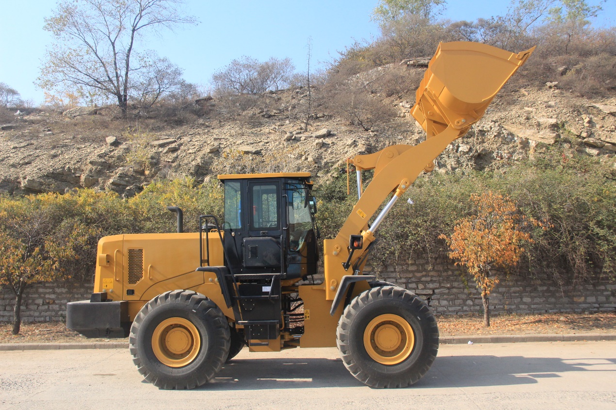
The shoveling and loading and unloading operations of the loader are realized through the movement of its working device. The working device of the loader is composed of a bucket 1, a boom 2, a connecting rod 3, a rocker arm 4, a bucket cylinder 5, and a boom cylinder. The whole working device is hinged on the frame. The bucket is connected to the bucket oil cylinder through the connecting rod and the rocker arm to load and unload materials. The boom is connected with the frame and the boom cylinder to lift the bucket. The flipping of the bucket and the lifting of the boom are hydraulically operated.
When the loader is working, the working device should be able to ensure that: when the bucket cylinder is locked and the boom cylinder is lifted or lowered, the connecting rod mechanism makes the bucket move up and down in translation or close to translation, so as to prevent the bucket from tilting and spilling materials; When the boom is in any position and the bucket rotates around the pivot point of the boom to unload, the inclination angle of the bucket is not less than 45°, and the bucket can be automatically leveled when the boom is lowered after unloading. According to the structural types of loader working devices at home and abroad, there are mainly seven types, that is, according to the number of components of the connecting rod mechanism, it is divided into three-bar type, four-bar type, five-bar type, six-bar type and eight-bar type; According to whether the steering direction of the input and output rods is the same, it can be divided into forward rotation and reverse rotation linkage mechanisms. Loader bucket structure for earthwork, the bucket body is usually welded with low-carbon, wear-resistant, high-strength steel plates, the cutting edge is made of wear-resistant medium-manganese alloy steel rice bucket, and the side cutting edges and reinforced angle plates are made of high-strength Made of wear-resistant steel material.
There are four types of bucket cutter shapes. The choice of tooth shape should consider factors such as insertion resistance, wear resistance and ease of replacement. The tooth shape is divided into sharp teeth and cog teeth. The wheel loader mostly uses sharp teeth, while the crawler loader mostly uses blunt teeth. The number of bucket teeth depends on the bucket width, and the bucket tooth spacing is generally 150-300mm. There are two types of bucket tooth structures: integral type and split type. Small and medium-sized loaders mostly use integral type, while large loaders often use split type due to poor working conditions and serious wear of bucket teeth. The split bucket tooth is divided into two parts: basic tooth 2 and tooth tip 1, and only the tooth tip needs to be replaced after wear and tear.
Post time: Jun-28-2023